Today,we are learning to implement PWM (pulse width modulation) using AT89s52, a microcontroller from 8051 family. Pulse Width Modulation can be used to vary the speed of a DC motor varying the width of the pulse provided to motors.Increasing the width of pulse provided to the motor increases the speed of the motor while decreasing the width of the pulse supplied to the motor decreases the speed of the motor.
Since , no PWM dedicated pins are available in AT89s52 (8051 family) microcontroller, it is our task to create the required duty cycle in the source code section.
Duty cycle which is measured in percentage is the period for which the pulse is high in the total cycle of signal whose mathematical expression is shown below.
Duty cycle= Period for which the pulse is high / Total cycle
Thus, 50% duty cycle reduces the speed of the motor by 50% since only half of the applied power is delivered to the motor.
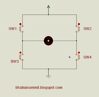
Hardware section:- In this section I will explain about the hardware component used.Since, in most of the application which uses motors for eg in field of robotics , we desire the motor to move in both clockwise and anti-clockwise direction, H-Bridge motor driver will be the most favorable option to use. some example of H-Bridge are L293D , L298 etc which can drive motor having current rating of maximum 2 Amperes. But if you don't have an intention of using readily available ICs or if these ICs doesn't fulfill your current requirement then you can built your own H-Bridge. The working principle of H-Bridge is discussed below.
When switches sw1 and sw4 are closed motor rotates in clockwise direction.
When switches sw2 and sw3 are closed, motor rotates is anti-clockwise direction.
When all switches are open motor doesn't rotate.
When all switches are closed, its an invalid operation.
Software section:- Keil uvision is used to write source code and generate intel HEX code. The microcontroller used to control the operation is AT89s52.
Below is the description of routine used to genetate PWM.
The above routine takes cent_per and req_duty as an input parameter, req_duty is the variable to hold the value of required duty cycle and cent_per holds value 100. As shown in above routine, if the count is below required duty cycle microcontroller enables the motor and motor revolves according to the instruction written in main program else microcontroller disables the motor thus stopping the rotation. Below is the snap taken from proteus .
Since , no PWM dedicated pins are available in AT89s52 (8051 family) microcontroller, it is our task to create the required duty cycle in the source code section.
Duty cycle which is measured in percentage is the period for which the pulse is high in the total cycle of signal whose mathematical expression is shown below.
Duty cycle= Period for which the pulse is high / Total cycle
Thus, 50% duty cycle reduces the speed of the motor by 50% since only half of the applied power is delivered to the motor.
Hardware section:- In this section I will explain about the hardware component used.Since, in most of the application which uses motors for eg in field of robotics , we desire the motor to move in both clockwise and anti-clockwise direction, H-Bridge motor driver will be the most favorable option to use. some example of H-Bridge are L293D , L298 etc which can drive motor having current rating of maximum 2 Amperes. But if you don't have an intention of using readily available ICs or if these ICs doesn't fulfill your current requirement then you can built your own H-Bridge. The working principle of H-Bridge is discussed below.
 |
| fig:- H-Bridge |
When switches sw1 and sw4 are closed motor rotates in clockwise direction.
When switches sw2 and sw3 are closed, motor rotates is anti-clockwise direction.
When all switches are open motor doesn't rotate.
When all switches are closed, its an invalid operation.
Software section:- Keil uvision is used to write source code and generate intel HEX code. The microcontroller used to control the operation is AT89s52.
Below is the description of routine used to genetate PWM.
 |
| figure:- PWM routine |
The above routine takes cent_per and req_duty as an input parameter, req_duty is the variable to hold the value of required duty cycle and cent_per holds value 100. As shown in above routine, if the count is below required duty cycle microcontroller enables the motor and motor revolves according to the instruction written in main program else microcontroller disables the motor thus stopping the rotation. Below is the snap taken from proteus .
 |
| figure:- snap from proteus. |
NOTE:- Isolation circuitry is not shown in the figure above but i strongly recommend you to use isolation circuit which isolate the microcontroller circuit and the motor driver circuit.And this isolation circuit
prevents the microcontroller from the back emf produced by the motor.
To download the complete source code with proteus simulation file, click here.
3 comments:
thank you very much but ı can not find proteus similation file in this download link..Please upload this file ..Thank you very much again,have a nice day...
there is no proteus simulation file,please upload this file...
Thank you very much :D
I have uploaded it and you will require proteus 8 for it.
Post a Comment